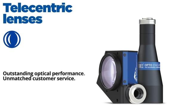
TCBENCH series
Telecentric optical benches for precision measurements


Key advantages
- Pre-assembled set-up
Just attach yor camera, and the bench is ready for measurement - Best optical performances
The bench is pre-set to provide unpaired measurement accuracy - Tested system
The bench is quality tested as a whole system - Detailed test report with measured optical parameters
TCBENCH series is a range of complete optical systems designed for hassle-free development of demanding measurement applications.
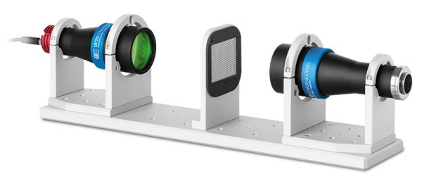
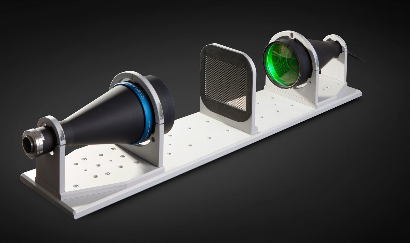
Each kit integrates:
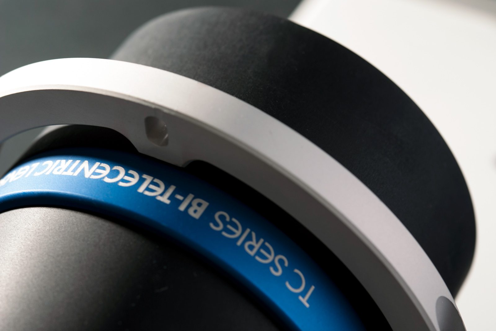
- 1 bi-telecentric lens for 2/3” detectors
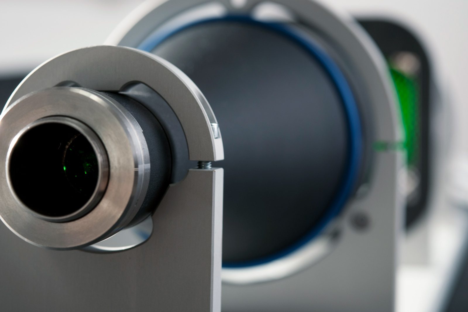
- 1 LTCLHP telecentric illuminator (green)
- 2 CMHO mechanical clamps
- 1 CMPT base-plate
- 1 PTTC chrome-on-glass calibration pattern
- 1 CMPH pattern holder
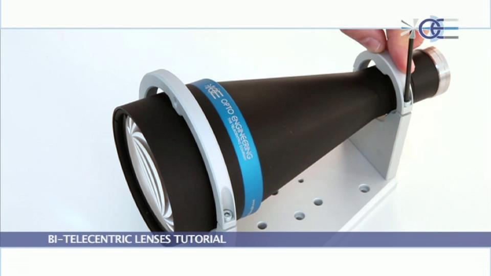
The benches come ready for use, pre-assembled and pre-aligned to assure the best accuracy that a telecentric measurement system can deliver.
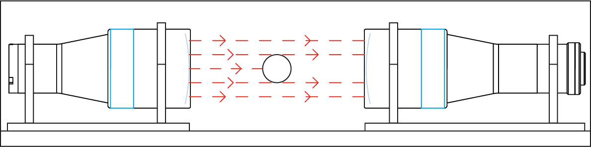
The collimated light source is set in order to optimize both illumination homogeneity and relevant optical parameters such as distortion, telecentricity and resolution. For this reason, these benches feature unmatched image resolution and depth of field.
Opto Engineering® measures the optical performance of each TCBENCH and provides an individual test report. TCBENCH series also benefits from a special price policy, combining high-end performance with cost-effectiveness.
DID YOU KNOW?
The TCBENCH series is now also available with new LTSCHP1W-GZ green light source, suitable for any kind of sample and specifically tailored for measuring reflective objects and objects with sharp edges.
KEY FEATURES
- Reduction of edge diffraction effects.
- Enhanced illumination uniformity, especially on large FOVs.
- Less sensitive to alignment.
Ordering information
To order the version with the new green LED module use part number TCBENCH0xx-0-GZ (i.e. TCBENCH064-0-GZ).
Notes
- Working distance: distance between the front end of the mechanics and the object. Set this distance within ± 3% of the nominal value for maximum resolution and minimum distortion.
- Working f-number (wf/N): the real f-number of a lens in operating conditions.
- Maximum angle between chief rays and optical axis on the object side. Typical (average production) values and maximum (guaranteed) values are listed.
- Percent deviation of the real image compared to an ideal, undistorted image. Typical (average production) values and maximum (guaranteed) values are listed.
- At the borders of the field depth the image can be still used for measurement but, to get a very sharp image, only half of the nominal field depth should be considered. Pixel size used for calculation is 3.45 μm.
- Object side, calculated with the Rayleigh criterion with λ= 520 nm
- At max forward current. Tolerance is ± 0.06V on forward voltage measurements.
- Used in continuous (not pulsed) mode.
- At pulse width <= 10 ms, duty cycle <= 10% condition. Built-in electronics board must be bypassed (see tech info).
- Measured from the camera flange of the objective lens to the electronic end of the illuminator. Cable, connector and mount thread excluded.
Features
The benches come pre-assembled and pre-aligned to assure the best accuracy that a telecentric measurement system can deliver. The collimating source is set in order to optimize both the illumination homogeneity and the relevant optical parameters (distortion, telecentricity, resolution). Opto Engineering® tests the optical performances of each TCBENCH and provides an individual test report certifying the measurement accuracy of the entire system.
Coupling a LTCLHP illuminator with a telecentric lens increases the natural field depth of the lens; this is particularly true for 2/3” detector lenses where the acceptance angle of ray bundles is much larger than the divergence of the collimating source. For this reason these benches feature unmatched image resolution and field depth. TCBENCH also benefit from a special price policy, combining high-end performances with cost effectiveness.

Instructions for use
Operation options
LTSCHP LED modules can be operated in two ways:
- standard usage option: through the built-in electronics
- direct LED control usage option
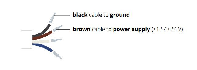
STANDARD usage option (LED control throuh built-in electronics)
Only conitinuous mode (constant voltage) is allowed.
Connection: connect the black and the brown cables to your +12 / +24 V power supply.
Light intensity adjustment
The built-in multi-turn trimmer allows to control the light (LED forward current) intensity with a very high degree of precision: you can bring the current intensity from minimum to maximum with 21 full turns of the adjustment screw. Simply remove the protective cap and rotate counter-clockwise the adjustment screw to increase light intensity and vice versa.

LED replacements
Direct LED control usage option
Both continuous and pulsed mode are allowed; the built-in electronics can be bypassed in order to drive the LED directly for use in continuous or pulsed mode. When bypassed, builtin electronics behaves as an open circuit allowing direct control of the LED source. Please note that in such case light intensity adjustment is not possible though the built-in multi-turn trimmer.
Connection: connect the black and blue cables as shown below (remove the LED anode protective cover).
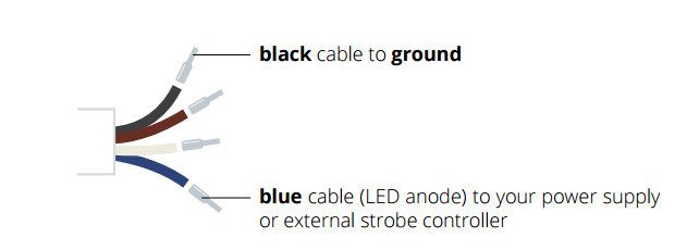
Make sure not to exceed LEDs maximum rates to avoid electrical shorts.